Design Guidelines for Plastic Parts
1. Introduction
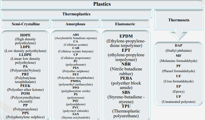
1.1 What are Plastics?
- Plastic materials contain a mixture of molecules
- The major portion is made up of large molecules known as polymers
- Remainder is composed of much smaller, widely differing types of molecules which are collectively referred to as additives
- Polymers are long chain molecules formed due to the reacting together or polymerisation of different organic materials called monomers
- Their composition always includes atoms of carbon, joined together, by primary covalent (electron sharing) bonds, to other atoms like hydrogen, oxygen, nitrogen, fluorine, silicon, sulphur, chlorine, etc
1.2 Sources of Plastics
- Sources of plastics are coal, petroleum & natural gas. Calcium carbide, ethylene, propane, benzene etc. are starting chemicals for producing synthetic resins
2. Types of Plastics
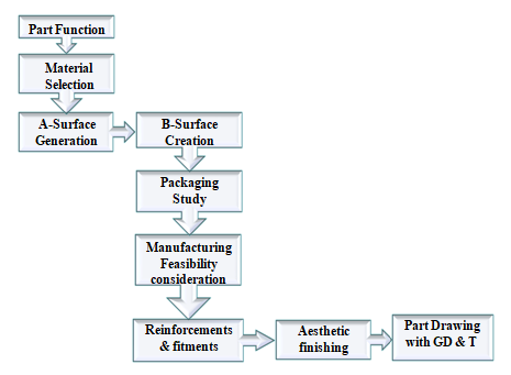
3. Overview of Design Process
- Part design process takes following steps into consideration
4. Inputs Required
- Most commonly required inputs for pat design are
- Point Cloud Data/ STL data
- Part specification ( Wall thickness, fitments etc.)
- Part assembly packaging
- Part function
5. Design Considerations
-
Important aspects to be considered while designing a plastic part are
- 5.1 Wall Thickness
- 5.2 Coring Out
- 5.3 Draft
- 5.4 Material Selection
- 5.5 Parting Line
- 5.6 Undercuts
- 5.7 Aesthetic Surface Finishing
5.1 Wall Thickness
- Wall thickness depends on shape, function and material used
- General range from 2 mm to 4 mm. Thin wall (injection molding ) ~ 0.5 mm
- Thinner wall cools faster, hence short cycle times => lowest part costs
- Avoids warpage and build-up of stress
- Easier to fill in the mold cavity
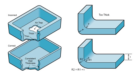
- Any transitions should be uniform
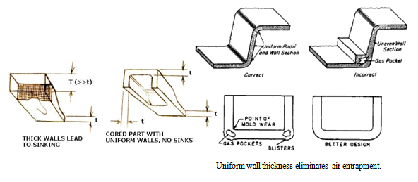
- Keep wall thickness as uniform as possible
- Use gradual transitions between thick and thin sections
- Wall thickness must suit both function and process
- Wall thickness guide range is:
- 0.75 mm to 3 mm for reinforced materials
- 0.5 mm to 5 mm for unreinforced materials
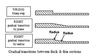
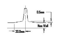
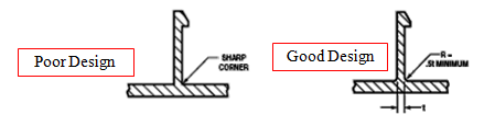
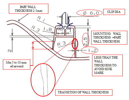
The transition should be very gradual. Local thickening is permissible up to 0.5 mm transitioned over a minimum of 30 mm in all directions.
5.1.1 Example of Wall Thickness
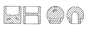
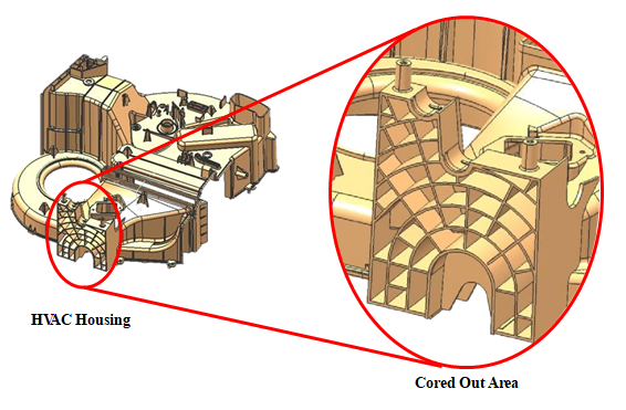
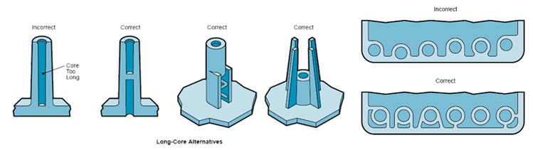
5.2 Coring Out
Coring out is removal of material from thick sections of part hence maintaining uniform wall thickness and avoiding defects.
- Coring out helps to maintain uniform wall thickness
- Leads to lesser usage of material
- Often stronger design by increasing rigidity
- Lesser cost
- Avoids sink mark and voids
- The dimension for coring implies same as what is given for ribs
5.2.1 Example of Coring Out
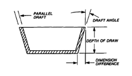
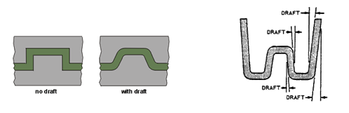
5.3 Draft
Draft is the angle between the part ejection direction and
the surface of the part.
- While giving draft to ribs or any wall, consideration should be given to height of ribs or walls
- If the height of rib is less, then the draft can be increased & vice versa
- Facilitates part removal from the mold
- General draft 0.5 - 2 degrees
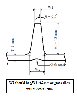
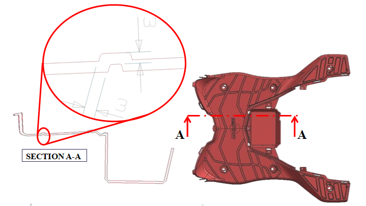
5.3.1 Example of Draft
In the example if the rib will have a min. top thickness of 1.5mm and draft of 0.5˚, then max. thickness at root of rib will be 2.2mm which would lead to sink mark.
Hence in this case we will have to either reduce the draft or height of the rib.
General thumb rule is – Maintain the top(W1) and bottom(W2) of ribs thickness within the ratio of rib thickness to wall thickness of the part i.e. 50% to 60%.
Note:- If the sink mark is not an issue i.e. if the A-surface is not visible part then we can go for a stronger ribs.
5.4 Material Selection
Material is selected depending upon function of part.
| Material name | Trade names | Material Properties | Applications |
|---|---|---|---|
| Acetal (POM) | Celcon, Delrin, Hostaform, Lucel | Strong ,rigid, excellent fatigue resistance, excellent creep resistance, chemical resistance, moisture resistance, naturally opaque white, low/medium cost | Bearings, cams, gears, handles, plumbing components, rollers, rotors, slide guides, valves |
| Acrylic (PMMA) | Diakon, Oroglas, Lucite, Plexiglas | Rigid, brittle, scratch resistant, transparent, optical clarity, low/medium cost | Display stands, knobs, lenses, light housings, panels, reflectors, signs, shelves, trays |
| Acrylonitrile Butadiene Styrene (ABS) | Cycolac, Magnum, Novodur, Terluran | Strong, flexible, low mold shrinkage (tight tolerances), chemical resistance, electroplating capability, naturally opaque, low/medium cost | Automotive (consoles, panels, trim, vents), boxes, gauges, housings, inhalers, toys |
| Cellulose Acetate (CA) | Dexel, Cellidor, Setilithe | Tough, transparent, high cost | Handles, eyeglass frames |
| Polyamide 6 (Nylon) (PA6) | Akulon, Ultramid, Grilon | High strength, fatigue resistance, chemical resistance, low creep, low friction, almost opaque/white, medium/high cost | Bearings, bushings, gears, rollers, wheels |
| Polyamide 6/6 (Nylon) (PA6/6) | Kopa, Zytel, Radilon | High strength, fatigue resistance, chemical resistance, low creep, low friction, almost opaque/white, medium/high cost | Handles, levers, small housings, zip ties |
| Polyamide (Nylon) (PA11+12) | Rilsan, Grilamid | High strength, fatigue resistance, chemical resistance, low creep, low friction, almost opaque to clear, very high cost | Air filters, eyeglass frames, safety masks |
| Polycarbonate (PC) | Calibre, Lexan, Makrolon | Very tough, temperature resistance, dimensional stability, transparent, high cost | Automotive parts, bottles, containers, housings, light covers, reflectors, safety helmets and shields |
| General purpose Polystyrene (GPPS) | Lacqrene, Styron, Solarene | Brittle, transparent, low cost | Cosmetics packaging, pens |
| Polyvinyl Chloride Plasticised (PVC) | Welvic, Varlan | Tough, flexible, flame resistance, transparent or opaque, low cost | Electrical insulation, house wares, medical tubing, shoe soles, toys |
| Polyester – Thermoplastic (PBT, PET) | Celanex, Crastin, Lupox, Rynite, Valox | Rigid, heat resistance, chemical resistance, medium/high cost | Automotive (filters, handles, pumps), bearings, cams, electrical components (connectors, sensors), gears, housings, rollers, switches, valves |
| Polyether Sulphone (PES) | Victrex, Udel | Tough, very high chemical resistance, clear, very high cost | Valves |
| Polyether ketone (PEEK) | Strong, thermal stability, chemical resistance, abrasion resistance, low moisture absorption | Aircraft components, electrical connectors, pump impellers, seals | |
| Polyethylene - Low Density (LDPE) | Alkathene, Escorene, Novex | Lightweight, tough and flexible, excellent chemical resistance, natural waxy appearance, low cost | Kitchenware, housings, covers, and containers |
| Polyethylene - High Density (HDPE) | Eraclene, Hostalen, Stamylan | Tough and stiff, excellent chemical resistance, natural waxy appearance, low cost | Chair seats, housings, covers, and containers |
| Polyphenylene Oxide (PPO) | Noryl, Vamporan, Thermocomp, | Tough, heat resistance, flame resistance, dimensional stability, low water absorption, electroplating capability, high cost | Automotive (housings, panels), electrical components, housings, plumbing components |
| Polyphenylene Sulphide (PPS) | Ryton, Fortron | Very high strength, heat resistance, brown, very high cost | Bearings, covers, fuel system components, guides, switches, and shields |
| Polypropylene (PP) | Novolen, Appryl, Escorene | Lightweight, heat resistance, high chemical resistance, scratch resistance, natural waxy appearance, tough and stiff, low cost. | Automotive (bumpers, covers, trim), bottles, caps, crates, handles, housings |
| Styrene Acrylonitrile (SAN) | Luran, Arpylene, Starex | Stiff, brittle, chemical resistance, heat resistance, hydrolytically stable, transparent, low cost | House wares, knobs, syringes |
| Thermoplastic Elastomer /Rubber (TPE/R) | Hytrel, Santoprene, Sarlink | Tough, flexible, high cost | Bushings, electrical components, seals, washers |
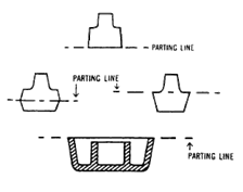
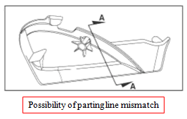
5.5 Parting Line
- Parting line Divides the part in to core half and cavity half, More specifically the moving and stationery parts of the mold
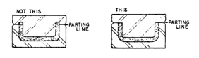
- Parting line should be designed such that the part has no or minimum undercuts
- The part should be designed so as to present a good parting line to the mold maker
- Flash is usually produced at the P/L and has to be finished manually or mechanically
- If the part is aesthetically important the P/L should be concealed on a thin inconspicuous edge of the part
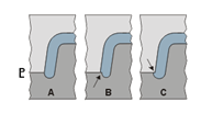
Possibility of parting line mismatch
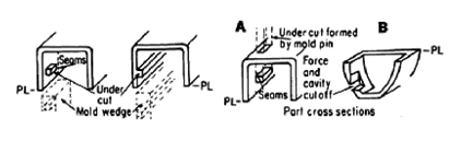
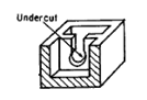
5.6 Undercuts
- Undercuts are any design features that creates hindrance to the normal opening of the mold
- Undercuts can be avoided by simple changes in design of part
- Inside undercuts can be made with removable wedges or ejector pins and ejector wedges
- Complicated undercuts need special mechanisms in mold

Mold
opening
direction
opening
direction

Ways to avoid Undercuts
- Mold knock-out pin through opening in part
- Cavity cutoff approaches
5.6.1 Example of Undercut
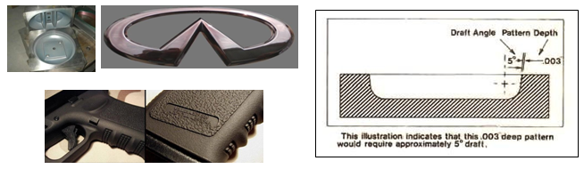
5.7 Aesthetic Surface Finishing
Reasons To Texture A Plastic Part
Visual Effect
Tactile Qualities
- To give the part the appearance of leather, wood, stipple, sand, or whatever material you are simulating
- To give the part a more even, planned effect, or to get rid of a glossy appearance and change to a matte finish
- To build into the appearance of the part a company‟s logo or a pattern that immediately identifies the part as belonging to that particular corporation
- To diffuse light on clear parts, such as serrations or frosting on a lens. Texture can also be used to make a clear part translucent
- For visual contrast - through the use of two different textures on one part or by frosting the background or foreground of a logo, for example texture can provide visual improvement of a tough to mold part
- Some textures just feel good to the touch or provide "grip," such as on a handle of a power tool, or handles for ski poles, etc.
- Adding texture to a core can help to hold the part onto the core without manual undercuts which could create sink marks
- Texture applied on the core side and across lifters and/or slides, for some materials, can hide the shadow marks which sometimes will show through from the front of the part when the Class "A" side is polished
- Texture is sometimes applied in order to better hold paint during a secondary molding operation
- Texture applied in the correct design and location can help to minimize turbulence created by plastic flow
- Texture can provide a functional rough surface finish, on a roll, for example to help the roll stock through the rolling process
- Texture adds strength to parts
- Texture adds thickness to the parts
- Non-slip textures can be applied to add safety measures to a part that requires that particular quality
- Texturing a fine texture on label areas of a part can help the labels to stick to the finished part
5.7.1 Aesthetic Surface Finishing (Texturing)
Texture depth and sidewall draft considerations
- To assure clean ejection of part, 1.5 – 2º of draft per .025mm texture depth is given
- Texture depth can be reduced in specific areas and/or the texture pattern can be „softened‟ on surfaces where there are ejection concerns
What tooling materials can be textured
- Standard tool materials such as P-20, H-13, S-7, 01, A1, A2, A6, 420 stainless, beryllium copper, forged, wrought and cast aluminums have all can be textured successfully
6. Reinforcements and Fitments
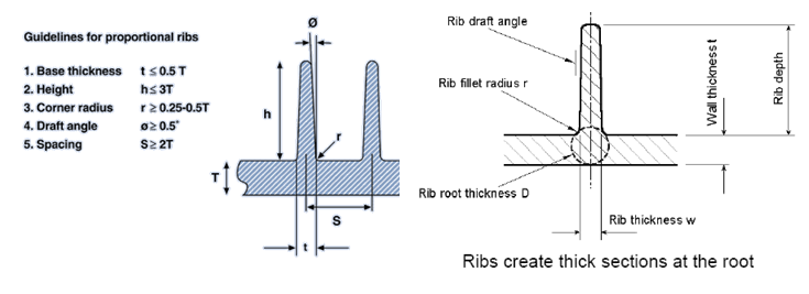
6.1 Ribs
Ribbing is typically applied for
- Increasing bending stiffness or strength of large flat areas
- Increasing torsional stiffness of open sections
6.1.1 Nominal Wall Ratio
The following shows the maximum rib to wall ratio for crystalline vs. non-crystalline materials considering Class A (“show”) vs. Class B (“non-show”) surfaces and structural vs. non-structural ribs
Semi-Crystalline material (PP, Celcon):
40% Rib to Wall ratio on Class A surface with non-structural rib.
45% Rib to Wall ratio on Class A surface with structural rib.
40% Rib to Wall ratio on Class B surface with non-structural rib.
50% Rib to Wall ratio on Class B surface with structural rib.
40% Rib to Wall ratio on Class A surface with non-structural rib.
45% Rib to Wall ratio on Class A surface with structural rib.
40% Rib to Wall ratio on Class B surface with non-structural rib.
50% Rib to Wall ratio on Class B surface with structural rib.
Amorphous material (ABS, PC, etc.):
50% Rib to Wall ratio on Class A surface with non-structural rib.
55% Rib to Wall ratio on Class A surface with structural rib.
50% Rib to Wall ratio on Class B surface with non-structural rib.
60% Rib to Wall ratio on Class B surface with structural rib.
50% Rib to Wall ratio on Class A surface with non-structural rib.
55% Rib to Wall ratio on Class A surface with structural rib.
50% Rib to Wall ratio on Class B surface with non-structural rib.
60% Rib to Wall ratio on Class B surface with structural rib.
- Structural: Feature performs a load-bearing function (e.g., part attachment, stand-off spacer, screw boss, clip rib, assembly locator, etc.)
- Non-Structural: Feature performs a non-load-bearing function (e.g., warp control, wall stock stiffener, provide gage point for part inspection, etc.).
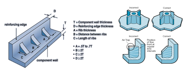
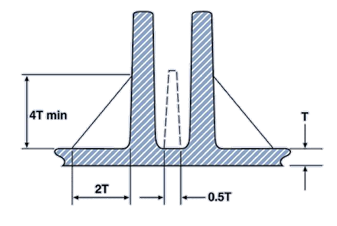
- The thickness of a rib should not exceed 50 - 70% the thickness of the nominal wall
- Maximum rib height should not exceed 5 times the nominal wall thickness
- Taper ribs for mould release. Typical draft is 1º to 1.5º per side with a min. of 0.5º per side
- At the intersection of the rib base and the nominal wall a radius should be provided 25% to 50% of the nominal wall section
- Parallel ribs should be spaced at a minimum distance of twice the nominal wall thickness
- Ribs are preferably designed parallel to the melt flow
- Ribs should be orientated along the axis of bending in order to provide maximum stiffness
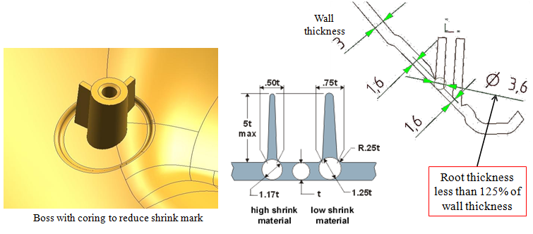
- Rib root thickness(D) should be max. 25% more than the nominal wall thickness
6.1.2 Example of Ribs
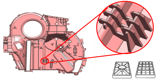
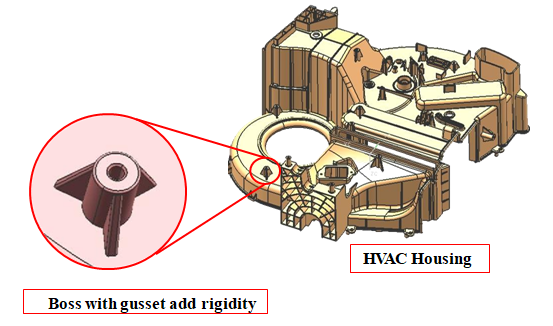
HVAC Housing
- Circular or diagonal ribbing eliminates twisting
- Bi-directional ribbing eliminates sagging or bending
6.2 Corrugations
Adding corrugations to the design can stiffen flat surfaces in the direction of the corrugations
The extra stiffness is a result of increasing the average distance of the material from the neutral axis of the part

Advantages:
- They are very efficient in adding stiffness to the part
- Do not add large amounts of extra material
- Do not lengthen the cooling time
6.2.1 Example of Corrugations
Corrugation is provided to increase the stiffness of the footrest board.
Footrest
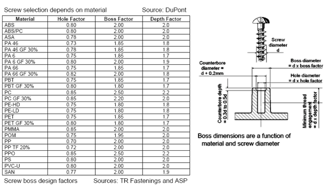
6.3 Boss
Purpose
- For locating mating parts
- For attaching fasteners
- Accepting threaded inserts
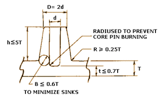
6.3.1 Boss Design Guidelines
- The wall thicknesses should be less than 60 % of nominal wall to minimize sinking
- The base radius should be a minimum of 0.25 x thickness
- The boss can be strengthened by gussets at the base and by attaching it to nearby walls with connecting ribs
- Avoid bosses that merge into sidewalls because they can form thick sections that lead to sink. Instead, position the bosses away from the sidewall, and if needed, use connecting ribs for support
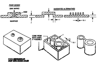
- The boss hole should extend to the base-wall level, even if the full depth is not needed for assembly. Shallower holes can leave thick sections, resulting in sink or voids. Deeper holes reduce the base wall thickness, leading to filling problems, knit lines, or surface blemishes
6.3.2 Coring Out in Bosses
Coring is done to avoid sink marks which might get created in thick sections near bosses.
- In case of bosses, sink marks can be observed below the boss due to accumulation of material
- To avoid the sink marks wall thickness around the bosses is reduced such that, base thickness is max. 25% more than part wall thickness
6.4 Holes
Holes are easily produced in molded parts by core pins.
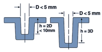
6.4.1 Blind Holes
Core pins supported by just one side of the mold tool create blind holes.
- The depth of a blind hole should not exceed 3 times the diameter
- For diameters less than 5 mm this ratio should be reduced to 2
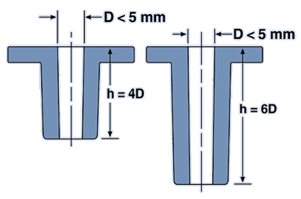
6.4.2 Through Holes
With through holes the cores can be longer, as the opposite side of the mold cavity can support, alternative is to use a split core fixed in both halves of the mold.
- The length of a given size core can be twice that of a blind hole
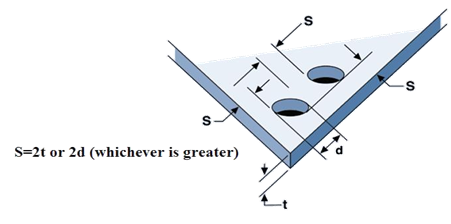
6.4.3 Minimum Hole and Hole Spacing Dimension
- The diameter of the hole should be no smaller than 1.5mm
- The length of the hole should be less than eight times its diameter
- The more draft on the hole - the better (minimum ½ degree in most cases)
- A fillet at the entrance to the hole greatly increases the strength of the core
- A deep hole can sometimes be split and drafted to each side
6.5 Radii and Corners
In the design of injection molded parts sharp corners should always be avoided & radii should be included in the design to reduce stress concentrations.
- Fillet radii should be between 25 and 60% of the nominal wall
- If the part has a load bearing function then the upper end is recommended
- A minimum radius of 0.5mm is suggested and all sharp corners should be broken with at least a 0.125 mm radius
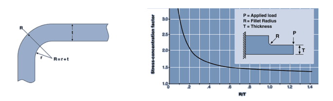
- The outside corner radius should be equal to the inside radius plus the wall thickness as this will keep a uniform wall thickness and reduce stress concentrations
- For a part with an internal radius half the nominal wall thickness a stress concentration factor of 1.5 is a reasonable assumption

6.5.1 Sharp corners, particularly internal corners lead to
- High molded in stresses
- Poor flow characteristics
- Reduced mechanical properties
- Increased tool wear
- Surface appearance problems
6.5.2 The inclusion of a radius will facilitate
- Uniform cooling
- Less war page
- Less flow resistance
- Easier filling
- Lower stress concentration
- Less notch sensitivity
6.6 Gussets
Gussets can be considered as a subset of ribs and the guidelines that apply to ribs are also valid for gussets. This type of support is used to reinforce corners, side walls, and bosses.
- The height of the gusset can be up to 95% of the height of the boss or rib it is attached to
- Depending on the height of the rib being supported gussets may be more than 4 times the nominal wall thickness
- Gusset base length is typically twice the nominal wall thickness
- Limit gusset thickness to one half to two-thirds the thickness of the walls to which they are attached if sink is a concern
- Specify proper draft and draw polishing to help with mold release
- Avoid designing gussets that could trap gasses and cause filling and packing problems
6.6.1 Example of Gusset
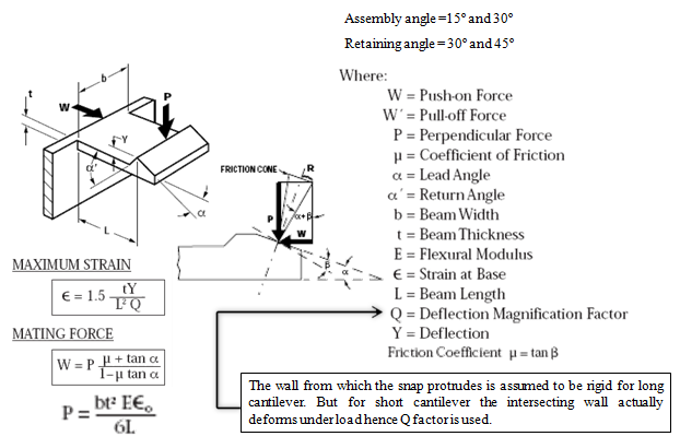
6.7 Snap Fit Joints
- An economical and quick method of joining plastic parts
- It is easily separated or inseparable, without breaking one of its components
- Whether the snap joint is a cantilever or a cylindrical fit, they both function similarly
- While designing snap-fit joints following things should be noted,
- The stresses applied to the snap beams after assembly
- The required stresses or strains on the snap beams during assembly
- The number of times the snap joint will be engaged and disengaged
- The number of times the snap joint will be engaged and disengaged
- The geometry of the snap

6.7.1 Reasons to Use Snap-Fits
- Reduces assembly costs
- Are typically designed for ease of assembly and are often easily automated
- Replaces screws, nuts, and washers
- Are molded as an integral component of the plastic part
- No welding or adhesives are required
- They can be engaged and disengaged
6.7.2 Things To Be Aware of When Using Snap-Fits
- Some designs require higher tooling cost
- They are susceptible to breakage due to mishandling and abuse prior to assembly
- Snap-fits that are assembled under stress will creep
- It is difficult to design snap-fits with hermetic seals. If the beam and/or ledge relaxes, it could decrease the effectiveness of the seal
6.7.3 Typical stress-strain curves for steel and unreinforced thermoplastic materials
- While metals can exhibit plastic behavior, they typically function within the elastic range of mechanical performance
- Because of visco-elasticity, unreinforced plastic materials tend to exhibit nonlinear behavior through much of their operating range
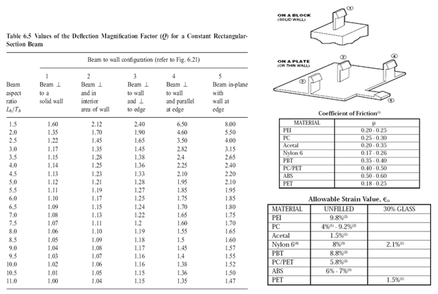
- Even at low strain values, plastics tend to exhibit some nonlinear behavior. As a result, using the tensile modulus or Young‟s modulus, derived from stress over strain in the linear region of the stress-strain curve, in structural calculations could lead to an error
- You may need to calculate the secant modulus, which represents the stiffness of a material at a specific strain or stress level
- Snap-fits fail due to stress concentration at sharp corner between the snap-fit beam and the wall to which it is attached
- This sharp corner location of maximum stress, can increase the stress beyond the strength of the material, causing point yielding or breakage
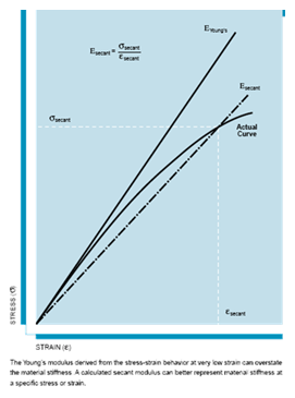
- This is more critical for rigid plastics like glass-reinforced nylon, which have relatively low ultimate elongation. More ductile materials, like unreinforced nylon, tend to yield and deform before they break, redistributing the peak stress over a broader region
- One solution is to incorporate a fillet radius at the juncture between the beam and the wall , so that the ratio of radius to wall thickness (R/t) is at least 50%. Going beyond 50% results in a marginal increase in strength and may cause other problems like internal voids and sink marks
- If sink marks are an issue, a smaller radius can be used, but it may increase the stress in this area. Another option is to add the radius only on the tensile side of the beam
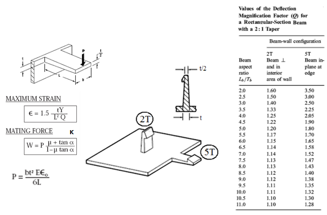
6.7.4 Example of Rectangular Snap Fit
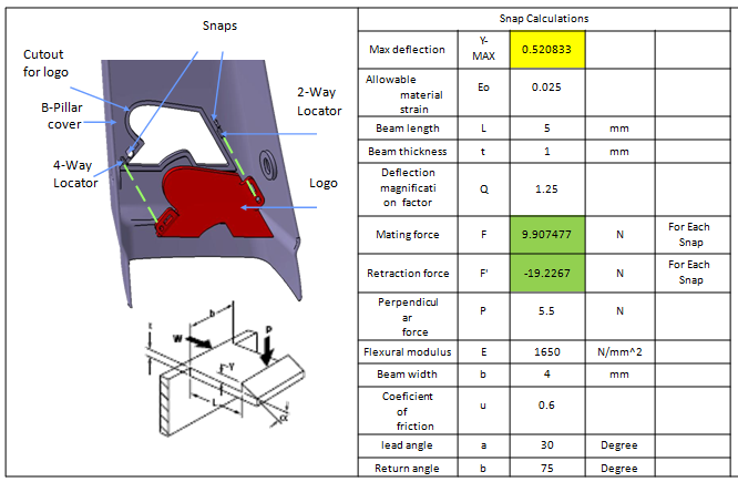
6.7.5 Tapered at Thickness Rectangular Snap Fit
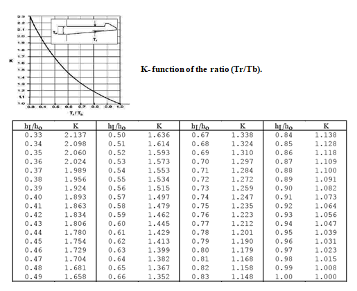
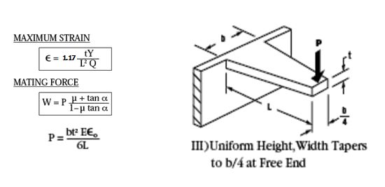
6.7.6 Tapered at width Rectangular Snap Fit
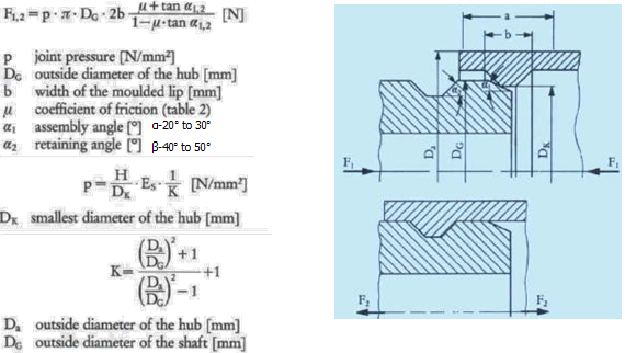
6.7.8 Cylindrical Snap Fit
Assumption:-The shaft is considered rigid and the hub elastic
The assembly force FI and pull-out force F2
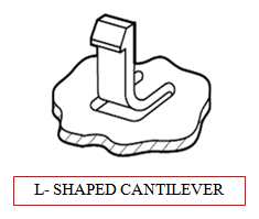
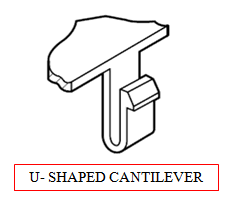
6.7.9 L and U Snap Fit
Occasionally, a designer will not be able to design a cantilever snap-fit configuration with a strain below the allowable limit of the intended material. This is usually due to limited packaging space which
can restrict the length of the snap. This is the ideal time to consider using either an “L" shaped snap or a “U”shaped snap

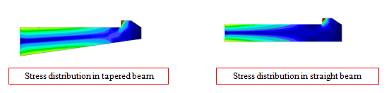
6.7.10 Comparison of Rectangular and Tapered Rectangular Snap Fit
- An improved method of designing cantilever beam snap-fits is to use a tapered beam. The beam is tapered from the root to the base of the snap foot
- Stresses in a straight beam concentrate at its base. Where as stresses in the tapered beam are distributed more uniformly through its length, therefore reducing stress, as shown in figure. The taper effectively decreases the beam's strain and allows for a deflection greater than that of a straight beam with the same base thickness
- Another use for a tapered snap beam is that when the straight beam is not stiff enough, the base of the beam can sometimes be increased to create a stiffer tapered beam
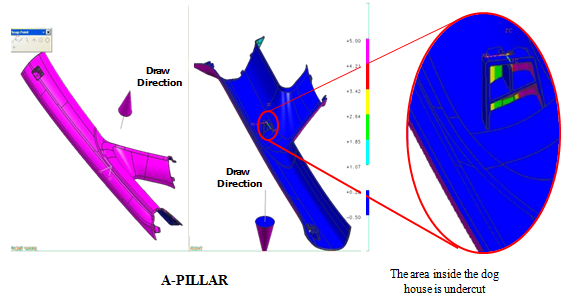
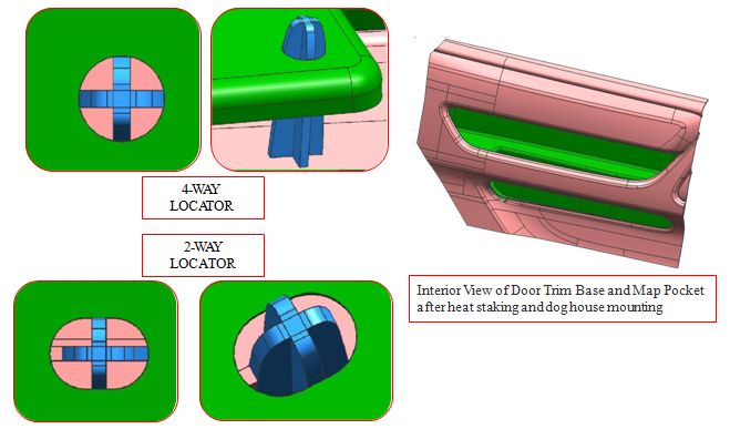
6.8 Dog House
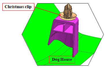
- Doghouse is used for mounting the plastic part on BIW panel with the help of Christmas clip
- Doghouse designs accommodate longer reaches from plastic “A” surface to metal structure in addition to providing retention features for separate piece fasteners
- Doghouse attachment is generally supplemented with mechanical fasteners for appropriate holding strength and retention
6.8.1 Advantages
- The doghouse is utilized during the JIT plant assembly process as a preliminary locator to “hang” the part prior to engaging supplemental mechanical fasteners
6.8.2 Dog House Forming Core
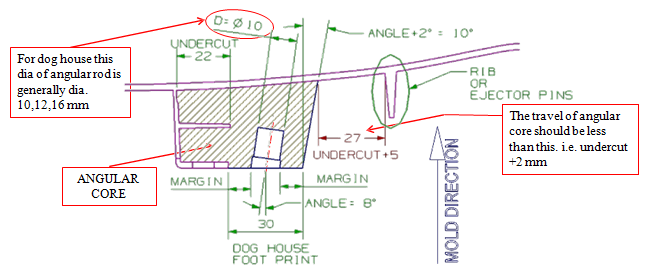
- Dog house foot print depends on the angular core rod dia ”D”. It should be sufficient such that the margin should not be weak
- Thumb rule is the margin should be equal to D where D is the angular core rod dia.(This value is only for smaller features like dog house, tower clip housing. For large angular cores as in bumper, more strength is required)
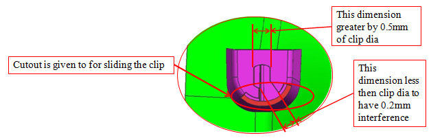
6.8.3 Dimensions of Dog House
6.8.4 Disadvantages
- The hidden design creates additional tool cost and complexity (slide action necessary to create dog house)
- As they are hidden fasteners, it is difficult to assure proper alignment during assembly and full engagement of the tree
- This fastening technique holds a part securely, but when removing part for serviceability, the part or the tree may get damaged
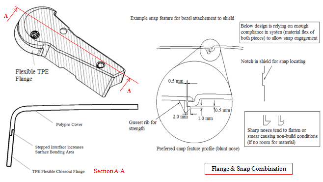
6.9 Flange
- Flanges are another name for sidewalls on a part and designed with the same thickness of the nominal wall
- Flanges are typically normal to die draw of tool. For this reason, draft is very important when designing them
- Flanges are also used to provide some feature along the side of the part (i.e. attachment hole, rib, etc.)
- Flanges provide structural rigidity to the part
- The longer the flange, the more noticeable the angle is and hence avoid larger flanges
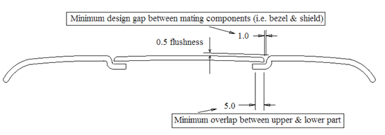
- The recommended (minimum) spacing between mating components and the overlap underneath is shown in the fig. The overlap allows for variations in gap size while maintaining uniform color appearance
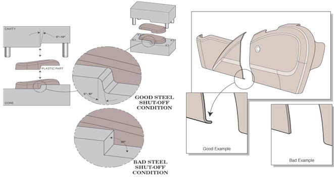
When the length of the flange varies, it is necessary to provide a shutoff angle for tooling. Shutoff angle is typically 5-10 degrees on flanges.
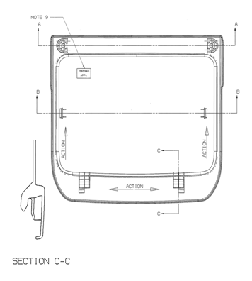
6.9.1 Example of Flange
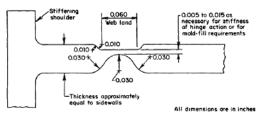
6.10 Live Hinge
- Hinges are very useful when a part is needed to enclose another part such as a mechanism
- A hinge is created by having a very thin section or channel along the line you want to bend. The section is generally 0.25-0.5 mm thick
- The part can be designed with a hinge that bends and some snaps are clipped to close the part. Proper hinge design must be followed or else the part will break instead of yield at the hinge line
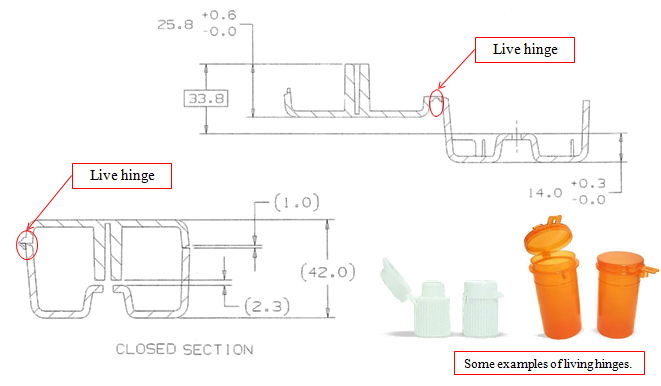
- Direction of flow of material should be perpendicular to hinge
- The gate should be positioned so that the material flows evenly over the hinge area. If more than one gate is used, the material SHOULD NOT meet in the hinge area. This would result in a weakened hinge with a high potential to break
- Used primarily in packaging products but can have engineering applications too
- Not all materials can be used for a hinge application. They are generally restricted to the olefinic materials (PP, PE, TPO, etc.). Materials such as Polypropylene can be molded with a living hinge
6.10.1 Example of Live Hinge
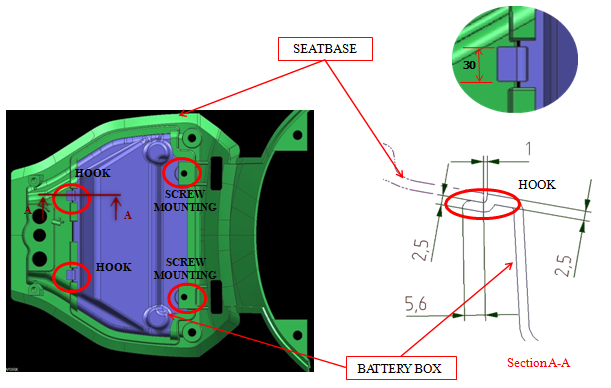
6.11 Hook
- Hook helps in locating the parts so that further positive clamping can be done
- The number of hooks depends on the dimensions of the part . The larger the part, increase the number of hooks
- The dimension for hook are similar to the flange design
- Hooks are generally supplemented with mechanical fasteners for appropriate holding strength and retention
- Hooks are commonly used in panel applications as a preliminary locator to “hang” the part prior to engaging supplemental mechanical fasteners during the JIT plant assembly process
6.11.1 Example of Hook
6.12 Heat Stake
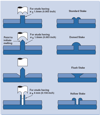
- Staking is a process suited to connect parts made from dissimilar materials e.g. plastic to metal
- One part is provided with studs or bosses which protrude through the holes in the other part. The stud or the boss is then deformed by melting the plastic to form ahead which mechanically locks the two parts together
- Quick and economical
- No consumables like rivets and screws required
- Applicable to thermoplastic materials including glass-filled materials
- The quality of the joint depends on processing parameters like
- Temperature of the material
- Pressure applied
- Time
- Stud diameter between 1.6 and 4mm is for general purpose
- Dome stake for small stud with diameter smaller than 1.6mm
- Flush stake is used where a flat surface is required
- Hollow stake minimizes sink marks and shrinkage voids and used where diameter is more than 4mm
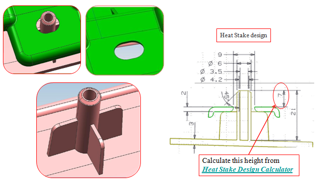
6.12.1 Example of Heat Stake & cutout arrangement
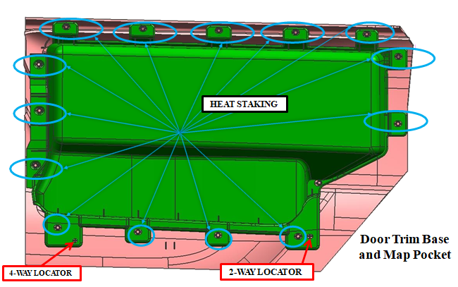
6.12.2 Example of Heat Stake & cutout arrangement
6.13 Locators
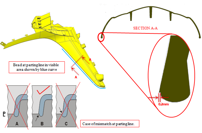
6.14 Bead
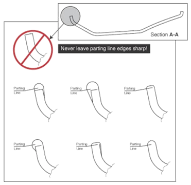
- Parts should have a beaded or rounded edge to eliminate any sharp edges
- The tangent point where the bead radius meets the wall. This makes matching the core and cavity halves of the tooling more difficult. Hence 0.2mm step is provided. See next slide for details
6.14.1 Example of Bead
7.Joining of Plastics
Joining techniques offer a cost-effective, aesthetically pleasing, and structurally sound solution for designing and manufacturing intricate parts
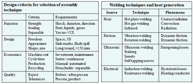
To design good assemblies following points should be noted
- A working knowledge of the selected plastic resin
- A fundamental knowledge of joint design
- A thorough understanding of the purpose, geometry, ambient environment
- Chemicals and mechanical loading which assembly will encounter
- Design for disassembly, an important factor for serviceability
- Design for disassembly, an important factor for serviceability
- Involving the designer, end user, materials supplier and molder throughout a project will make the transition from concept to finished part much easier
7.1 Types of Joining Plastics
- Ultrasonic Joining
- Hot Plate Welding
- Vibration Welding
- Self Tapping Screws
- Threaded Metal Inserts
- Fasteners
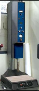
7.1.1 Ultrasonic Joining
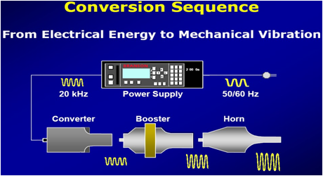
- An ultrasonic plastic assembly system converts standard electrical energy from 50/60Hz to 20 to 40 kHz and then into mechanical vibratory energy
- This vibration is amplified by a booster and transferred to the work piece through a tapered metal tool called a horn
- During the welding process, one of the two pieces to be joined is held stationary by a fixture while the horn is applied at a precisely controlled clamping pressure to the other piece
- Mechanical vibration causes frictional heat between mating parts thereby melting the plastic
- Total weld time is generally around 0.5-1.0 second
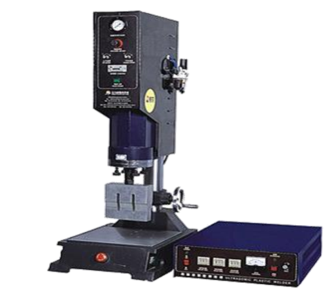
Ultrasonic Joining Machine
Advantages
- One of the most widely used joining techniques for thermoplastics
- Economical & can be fully automated
- High speed/high volume capability (generally less than two seconds/part)
- provides high strength joints (approaches original material strength)
- provides outstanding hermetic seal qualities
- potential multiple uses for original investment equipment (heat staking, swaging, and spot welding)
- Makes permanent, aesthetically pleasing joints
- High strength, clean weld seams, fast processing times, extremely low rejection rates and low energy consumption
Disadvantages
- Limited to small or medium sized components
- Components must be of same or similar plastic material
- Initial tooling investment can be expensive
- Susceptible to materials with moisture content
Types of Ultrasonic Joining Techniques
1. Ultrasonic Welding
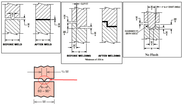
An energy director is a raised triangular bead molded on one of the joint surfaces. It concentrates ultrasonic energy causing a rapid initiation of the melt and welding of the material.
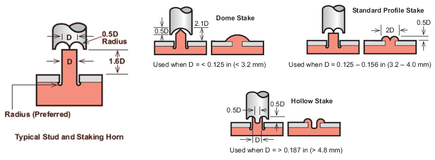
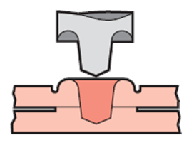
2. Ultrasonic Staking
- High-frequency vibrations from a specially contoured horn, melt the top of a thermoplastic stud which protrudes through a hole in the mating part of the assembly
- Mating material can be a dissimilar plastic or even metal. When the top of the stud melts, it forms a head that locks the two components together
- The base of the stud must be rounded to help reduce stress concentration
- The through hole on the mating part should be a close fit to prevent melt from flowing into the gap between the stud and the mating part
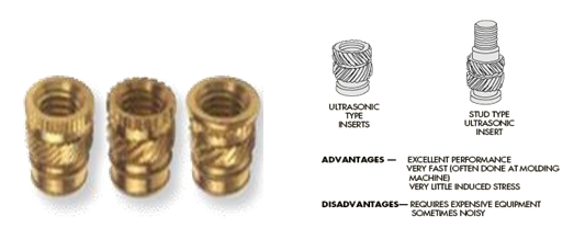
3. Ultrasonic Inserts
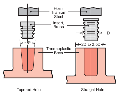
- This method uses the same equipment as ultrasonic welding
- The high frequency horn vibrations cause frictional heat between the insert and plastic, thereby melting it into the boss
- This process takes under 5 seconds and features low residual stress and excellent pullout strengths
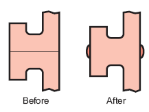
4. Ultrasonic Spot Welding
- No preformed holes or energy directors, ultrasonic spot welding joins two layers of thermoplastic resins with similar melting temperatures in a single location, forming a permanent bond
- The pilot tip melts through the first surface. As the tip penetrates the second or bottom surface, displaced molten plastic flows between the two surfaces, forming a bond
4.1 Example of Ultrasonic Spot Welding
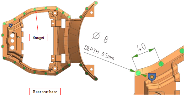
- Spacing between two snugets (40mm) & Snuget of diameter (8mm) depends upon size of horn
- Snugets are created for locating spot weld
- Detail specification is provided by vendor
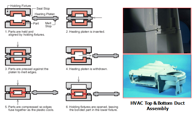
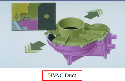
7.1.2 Hot Plate Welding
- For permanent, inexpensive joints, consider heat welding and sealing
- Hot plate welding is a direct thermal welding technique that uses a heated platen to contact the mating surfaces of the parts to be assembled until joint area melts
- The parts are then pressed together under slight pressure until the bond is set
- It is applicable to most thermoplastics, and is especially effective on semi-crystalline resins such as polyethylene and polypropylene
- Although some residual plastic called “flash” may detract from the part‟s appearance, heat welding can be used on parts where aesthetics are not important
Advantages
- Suited for large and complex parts
- More tolerant on material compatibility
- High strength hermetic seal
- Flash is smooth and fully attached
Disadvantages
- High utility cost
- Slow process (50 s)
- Residual plastic stick to tools
- Visible flash
- Tool change difficult
Hot Plate Welding Process
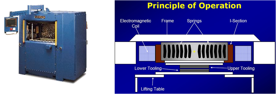
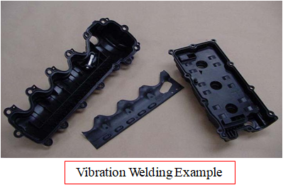
7.1.3 Vibration Welding
- It is a friction-welding technique
- Vibration welding uses a machine that operates at a frequency of either 120 or 240 Hz with a small displacement of 0.030 to 0.140 inch (0.7 to 3.5 mm)
- One part is fixed in a stationary head, while the second part, attached to a welding head, vibrates on the joint plane
- Pressing the two parts‟ surfaces together at a pressure of 200 to 245 psi (1.4 to 1.7 MPa) and vibrating one against the other generates heat
Advantages
- Welds complex, irregular shapes, Larger parts
- High-strength hermetic seals
- Can weld multiple parts
- Most thermoplastics can be welded
- Fast cycle time (typically 12-15 second total machine cycle time)
- Some dissimilar materials can be welded: PC to ABS, ABS to Acrylic
Disadvantages
- Limited to flat joint areas (less than 10 deg)
- Lateral motion of 2 mm
- Difficult to weld thin wall
- Produces particulates
- Flash trap required (increase wall thickness)
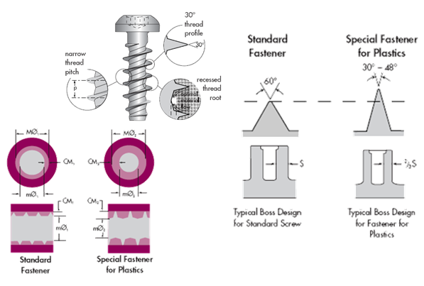
7.1.4 Self Tapping Screws
- Two main types : Thread cutting and Thread forming
- Thread cutting screws are generally used only on brittle Plastics, such as thermosets and highly filled (+50%) thermoplastics
- They cut threads by means of a slotted shank. Because they actually remove material when inserted
- Thread cutting screws should not be reinstalled and a chip reservoir should be added
- Thread forming screws are generally preferred for most thermoplastic applications
- These types of screws can be reinstalled a limited number of times (3-7)
- For repeated assembly and disassembly, some form of metal insert should be used
- There are several styles of thread forming screws designed specifically for plastics
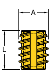
7.1.5 Threaded Metal Inserts
Threaded metal inserts are used when the assembly application requires repeated assembly and disassembly or the assembly needs to resist creep and compressive relaxation.
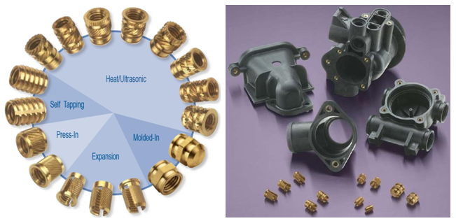
There are several methods of installing inserts:
1.Ultrasonic
- This method uses the same equipment as ultrasonic joining
- This process takes under 5 seconds and features low residual stress and excellent pullout strengths
- The Insert is placed into the hole and the horn of the ultrasonic inserter is pressed down on the Insert
- The horn transmits ultrasonic vibration to the Insert and the friction from the vibration of the Insert melts a thin film of plastic to the metal-plastic interface
- Pressure from the horn forces the Insert into the hole. When the horn is removed, the melted plastic next to the Insert solidifies
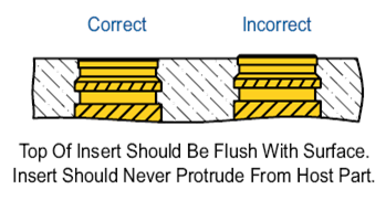
- The Inserts should be installed flush with the surface
- The horn travel needs to be limited either mechanically or with switches
2.Thermal
- The insert is melted into the boss where the insert is heated by a device like a soldering iron
- This method is relatively slow and also yields a low stress assembly with good pull out strengths
- Heat installation is a highly versatile method to install Inserts into thermoplastics with only temperature and pressure as variables
- Care has to be taken to assure that the heated Insert softens and not melts the plastic. This will avoid flash and keep the Insert in place as the plastic re-solidifies
- A piloted tip should be used to guide the Insert during installation and extended tips provide access to recessed holes
- The Insert should be installed flush with the surface, and this is usually accomplished with a positive stop
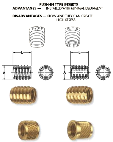
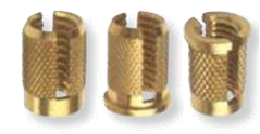
3.Self-Tapping
- These inserts have an external self-tapping screw thread and are driven into the hole using low cost equipment
- Self-Tapping Inserts provide the best pull-out resistance for a post-mold installed Insert
- The threads are designed with a thin profile to minimize inducing stress into the plastic and a relative coarse pitch to provide the maximum plastic shear surface to resist pull-out
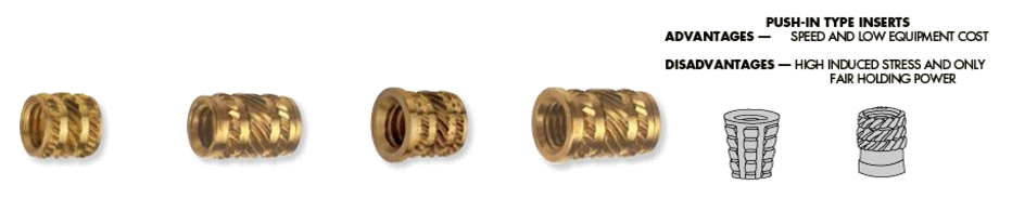
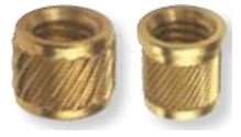
4.Press-Fit Inserts
- The insert is pressed in with an interference fit
- Place the Insert pilot into the hole and use a hammer or arbor press to seat it
- A piloted, extended punch can be used for recessed locations. In high volume applications, an automatic Insert Driver can be used to feed the Inserts into position and press them into place
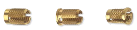
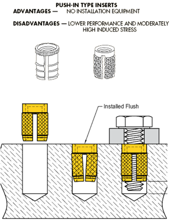
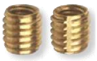
5.Expansion Inserts
- The expansion insert is designed to expand into the side walls of the boss with a tool
- Inserts are pressed into the plastic and expand when the assembly screw is tightened
- The sharp diamond knurling provides resistance to tensile and torque loads
- The mating screw should be designed for full thread engagement. This will allow the insert to fully expand
- A high stress imparted to the boss may lower mechanical performance
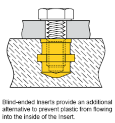
6.Molded-In Inserts
- Threaded insert is designed to be molded into the plastic component during the molding cycle
- The insert is placed on a core pin in the mold during the molding cycle
- The insert is designed with knurling and undercuts to resist rotational and tensile pull loads
- The part has a closed bottom (blind thread) to eliminate plastic flow into the threads
- This process, generally more costly in getting the Insert into place than the post-mold installation process, provides the best performance
Summary
1.Heat/Ultrasonic Inserts
- Designed for post-mold installation in thermoplastics
- Heat and ultrasonic installation yield outstanding performance results
- Use long inserts for maximum torque and pull-out resistance
- Short for less stringent requirements with the benefits of lower cost and reduced installation time
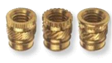
2.Self-Tapping Inserts
- Thread Forming Insert for thermoplastics and softer, flexible plastics
- Thread Cutting for thermosets and harder plastics
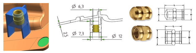
3.Press-In Inserts
- Ideal for use in softer plastics to provide a reusable thread which can meet the tightening torque requirements for a threaded joint
- Moderate pull-out and good torque requirements are provided by the helical knurl which also facilitates good plastic flow
- Easy and quick to install
4.Expansion Inserts
- Provide permanent, reusable threads for light duty applications
- Insertion of the screw expands the Insert pressing the knurl surface into the hole wall
Design Guidelines for Metal Inserts
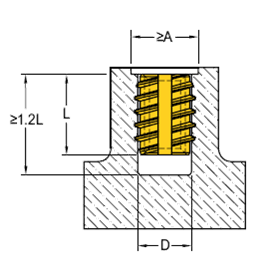
1.Holes
- For post-mold installed Inserts should always be deeper than the length of the Insert
- For Self-Tapping Inserts, a minimum depth of 1.2 times the Insert length is recommended
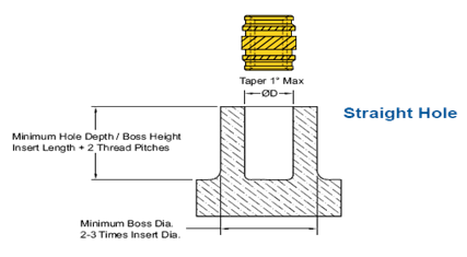
- For other Inserts, the recommended depth is the Insert length plus two (2) Insert thread pitches
- The assembly screw should never bottom out on the hole
2.Counterbores
- Recommended for Self-Tapping Insert holes. Reduces the risk of flaking
- The outside diameter of the counterbore should be equal to or larger than the outside diameter of the Self-Tapping Insert
- The depth should be one thread pitch
- For all other post-mold installed Inserts, a countersink or counterbore is not recommended
- The Insert pilot needs the hole edge to align the Insert axially square to the hole
3.Correct Hole Size
- Larger holes decrease performance
- Smaller holes induce undesirable stresses and potential cracks in the plastic
- Undersized holes may also result in flash at the hole edge
- The recommended holes need to be reviewed if fillers are used
- If the filler content is equal to or greater than 15%, it is suggested to increase the hole .003”, and if the content is equal to or greater than 35%, the suggested hole increase is .006”
4.Molded Holes
- Preferred over drilled holes
- The strong, denser surface of the molded hole increases performance
- For straight holes, the taper should not exceed a 1˚ included angle
- Tapered holes should have an 8˚ included angle
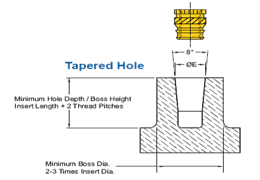
5.Tapered Holes
- Tapered holes reduce installation time and ensure proper alignment of the Insert to the hole
- Only tapered Inserts should be used in tapered holes
- Easier release from the core pin is an additional benefit
General Guidelines
- Insert performance is affected by the plastic boss diameter and wall thickness
- Generally the optimum wall thickness or boss diameter is two (2) to three (3) times the Insert diameter
- The wall thickness has to be enough to avoid bulging during installation
- Boss diameters to be strong enough for the recommended assembly screw installation torque
- Post-mold installed Inserts that are cold-pressed into the hole require larger boss diameters and wall thickness to withstand the greater stresses induced during installation. Installing the Inserts while the plastic is still warm from the molding process generally eliminates this need
- The diameter of the clearance hole in the mating component is very important
- The Insert should carry the load than plastic
- The hole in the mating component must be larger than the outside diameter of the assembly screw but smaller than the pilot or face diameter of the Insert. This prevents jack-out
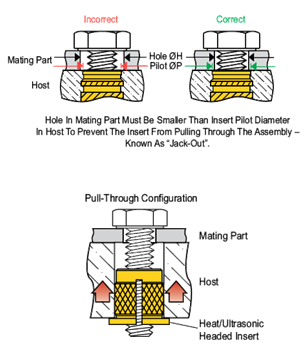
- For larger hole in the mating component for alignment purposes, a headed Insert should be considered
- Inserts should be installed flush in high load applications, locating the head opposite the load in a pull-through configuration requires design consideration
- The assembly screws for Expansion Inserts have to be long enough to fully penetrate the Inserts by at least two threads to achieve full expansion
7.1.6 Fasteners
1.Fascia / Trim Clips
- Used to retain fascias, dashboards and trim panels
- Utilized to aid speed and ease of assembly
- Designed for use on rectangular studs or integrally molded ribs on any lightweight application where removability is desired
- They provide a snug, rattle-free installation, yet will yield to deliberate removal force when required
- Typical applications include fascias, domestic appliances and motor vehicles
- Material - Austempered Carbon Steel
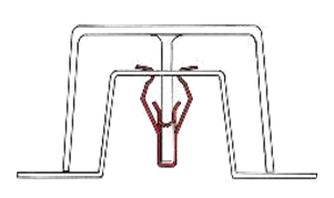
To facilitate removal or replacement, clips of type1 & type2 have barbs which enable them to remain on the trim panel but disengage from the base panel.
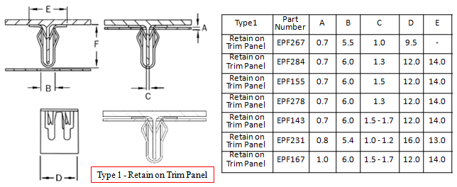
Type-1
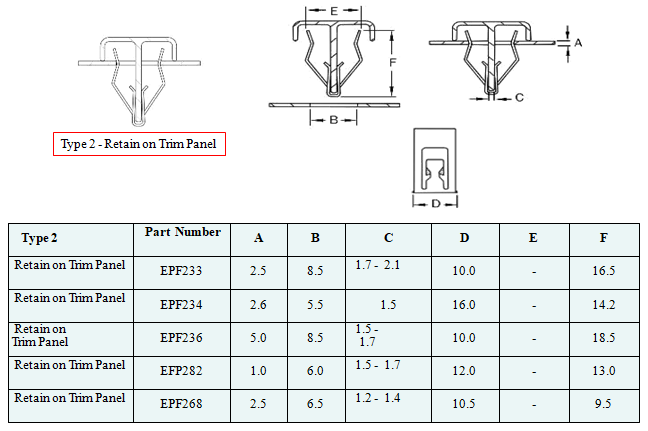
Type-2
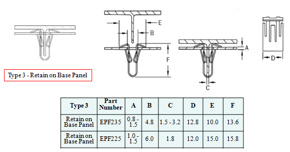
Type 3 clips are designed to remain fitted to the base panel but separate easily from the trim panel
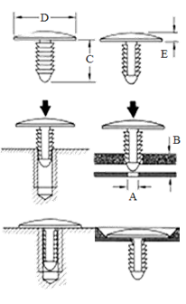
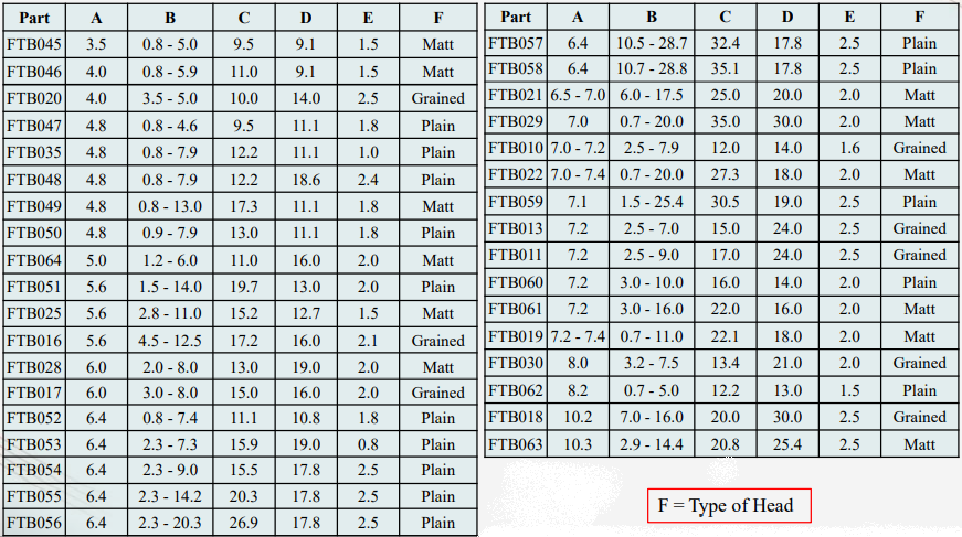
2.Fir Tree Buttons
- Push in Fir Tree Button Fasteners are designed to secure board, rubber or other soft sheet materials to secondary panels or for holding components to panels
- The button contracts on entry and then relaxes to secure the two panels
- Simple and quick to install
- Used extensively to secure trims in the automotive industry and have many other applications in domestic appliances and electrical equipment
- Typical applications include motor vehicles, domestic appliances, caravans and office furniture
Material - Nylon
Typical Colors - Black, Grey

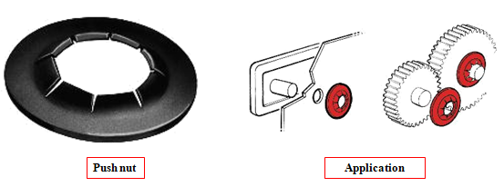
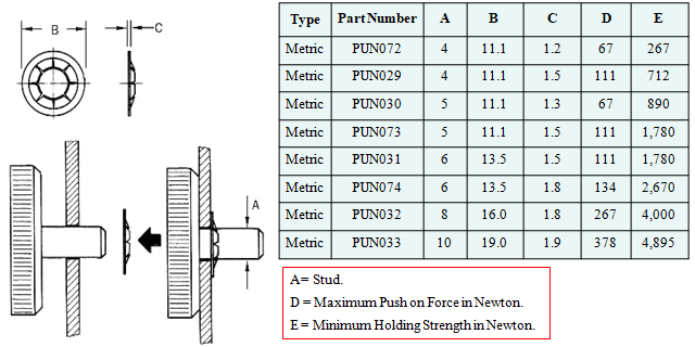
3.Push Nuts - Flat Round - Metric
- Most economical fastener
- It provides a good balance between maximum holding strength and reasonable push on force
- Push nuts can be applied with maximum speed, since pushing on especially with an air hammer is much faster than running down nuts
- Typical applications include motor vehicles, domestic appliances, toys and golf trolleys
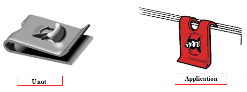
4.Push Nuts – U nut- Metric
- U-Nuts provide a strong and secure fixing for applications where two or more panels require holding together
- All types feature a generous lead-in for easy assembly, and use self tapping screws for fast fixing
- Typical applications include motor vehicles, domestic appliances, electrical equipment and machinery
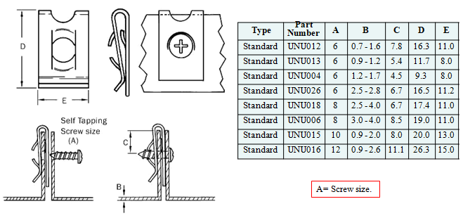
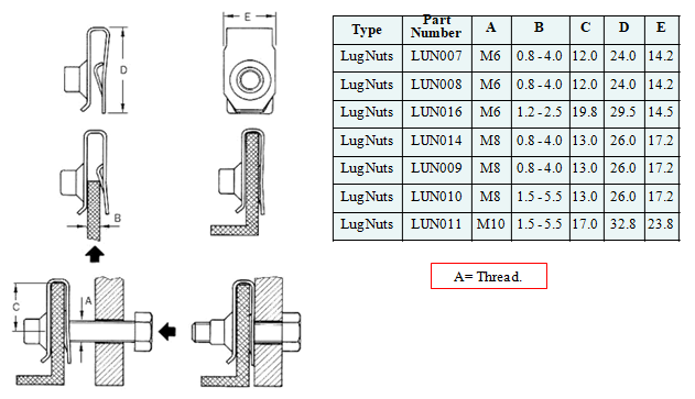
5.Push Nuts – Lug nut- Metric
- Lug Nuts are ideal in heavy duty applications where pressed U-Nuts are not strong enough. They offer a strong, reliable fixing in sheet materials
- Manufactured from carbon steel in one piece with a rolled thread
- Typical applications include motor vehicles, domestic appliances, heavy duty electrical installations, electrical equipment and machinery
- Part numbers LUN007 and LUN014 have an anti-vibration (Prevailing Torque) feature to prevent the screw loosening under vibration
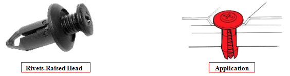
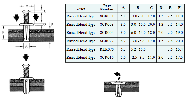
6.Plastic Rivets – Raised Head Type
- Ideal for applications where maintenance or servicing is required
- Fitting is achieved by driving the integral screw into the body, whilst removal is effected by means of a screwdriver
- Typical applications include motor vehicles, domestic appliances, audio equipment, boats and furniture
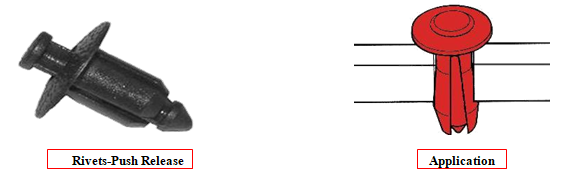
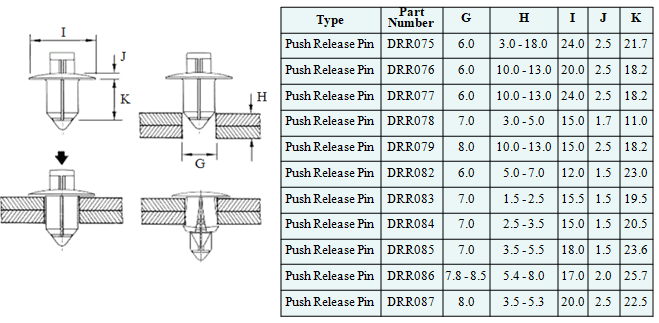
7.Plastic Rivets-Push Release Pin
- The Push Release Pin Drive Rivet is placed into the panel and the expansion pin pushed down to secure in place
- Typical applications include audio equipment, furniture, telecom equipment, motor vehicles, electrical equipment and domestic appliances
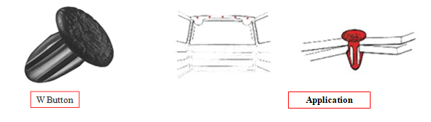
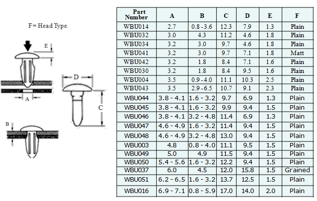
8.W Button Fasteners
- W Button Fasteners are designed to secure sheet materials to secondary panels and can also be used to hold components to panels
- The button is pushed through the aligning panel holes, contracting on entry and then relaxing to secure the two panels firmly together
- Typical applications include motor vehicles, domestic appliances, furniture, aerospace and caravans
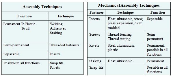
Assembly Techniques
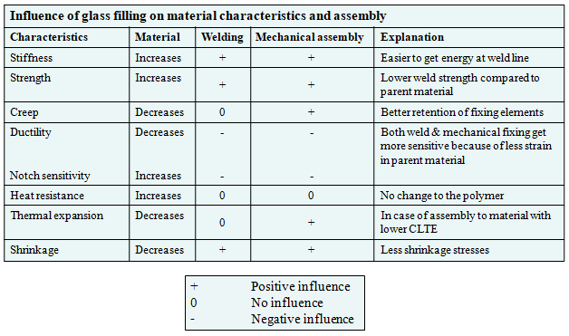
Influence of Glass Filling
8. Reference Books
| Sr. No. | Book Title | Link |
|---|---|---|
| 1 | GD & T | Read Book |
9. Reference Videos
| Sr. No. | Title of Videos | Link |
|---|---|---|
| 1 | Dog House Parametes and Relations | Open Video |
| 2 | Dog House Power Copy | Open Video |